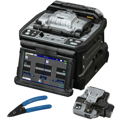
The Fujikura 90S+ core alignment fusion splicer solves common problems seen in the field—from splicing poor quality legacy fiber to automated equipment maintenance and upkeep. The Fujikura 90S+ can be use in multiple field splicing applications including bend-insensitive fibers in drop cables, long-haul terrestrial and submarine LEAF® fibers, loose buffer fiber, splice-on connectors, and the list goes on. The speed and accuracy of the 90S+ make it suitable for certain production and specialty environments where high output, tight packaging, and low loss requirements are required.
The 90S+ is packed with a whole host of new and enhanced features, specifically developed to enable faster splice cycle times with higher precision.
| Key Features |
|
| Automatic Open-Close Wind Protectors | The faster automated features of the 90S+ fusion splicer reduce installation times.
With this splicer, an operator can complete the entire splice process from splicing to heating without touching the 90S+ and only moving the fiber.
|
| Operation Time Reduction | The shape of the sheath clamp is optimized for 60mm length protection sleeves.
The length from splice point to the edge of the sheath clamp is 30mm. Therefore, it is easy to center the protection sleeve over the splice by using your fingers to reference the splice point.
|
| Fiber Retention Clamp | The fiber retention clamps support the automated operations.
When the sheath clamps open automatically after splicing, the fiber retention clamps gently hold the spliced fiber to keep it from flying out.
The retention clamps release when the fiber is lifted by the operator.
|
| Operation Time Reduction | These functions enable the 90S+ fusion splicer to reduce operation time by 50% over the previous model. |
| Carrying Case | There are multiple ways to utilize the 90S+ fusion splicer carrying case.
The 90S+ fusion splicer is ready to use just by opening the case, but it is also possible to use the 90S+ fusion splicer on top of the carrying case or only with the work tray depending on the work environment.
|
| Work Tray | The work tray has many functions. There are two drawers for storage, and the drawers are large enough to store tools or battery packs.
Also, the work tray can be divided in two, so it is configurable to fit your work space.
|
| Loose Tube Compatibility | The sheath clamp of the 90S+ fusion splicer is compatible with loose tube fiber.
The Protrusion part on of the sheath clamp for loose tube fiber engages or retracts by simply changing the switch position with your finger.
|
| Tool-Less Electrodes and Illumination | The 90S+ fusion splicer electrodes come as an “assy” including the fixing screw.
You can rotate the screw by hand without tools, enabling easy electrode replacement.
The transparent electrode covers support wider illumination of the v-groove. As the sheath clamp opens on the opposite side of the illumination lamp, the sheath clamp area is illuminated without shadow.
|
| Active Fusion Control Technology |
|
| Active Fusion Control by Cleave Condition | One of main causes of high splice loss is bad cleave end face. The 90S+ fusion splicer analyzes the condition of both L and R cleave end faces and performs optimal fusion control.
This new technology improves splice loss significantly and reduces the risk of re-installation.
|
| Active Fusion Control by Fiber Brightness | Fusion is easily affected by changes in the environment.
The 90S+ fusion splicer uses real-time fusion parameter control by analyzing the fiber’s brightness intensity during fusion. It contributes to stable, reduced splice loss.
|
| Active Fusion Control by Fiber Discrimination | Adequate splice parameters may differ depending on fiber type.
The 90S+ fusion splicer automatically applies the optimum splice parameters depending on the fiber type.
|
| Active Blade Management Technology |
|
| Active Blade Rotation by Motor | The 90S+ fusion splicer and CT50 fiber cleaver are enabled with wireless data connectivity.
This capability allows automatic cleaver blade rotation when the 90S+ fusion splicer judges the blade is worn.
The 90S+ fusion splicer can connect to two CT50s simultaneously.
|
| Active Blade Life Management | The 90S+ fusion splicer displays the remaining blade life and informs the user when a blade height change, position change, or new blade is required. |
| Specifications |
|
| Core Alignment Fusion splicer 90S+ |
|
| Features | Parameters |
| Fiber Alignment Method | Active core alignment |
| Fiber Count can be Spliced | Single fiber |
Applicable Fiber
Fiber Type
|
Single mode optical fiber
Multi mode optical fiber
|
Applicable fiber
Cladding Dia.
|
80 to 150μm
|
Applicable coating
Sheath Clamp
|
Coating dia. : Max. 3000μm
Cleave length : 5 to 16mm *1
|
Fiber splice performance
Splice Loss *2
|
ITU-T G.652 : Avg. 0.02dB
ITU-T G.651 : Avg. 0.01dB
ITU-T G.653 : Avg. 0.04dB
ITU-T G.654 : Avg. 0.04dB
ITU-T G.655 : Avg. 0.04dB
ITU-T G.657 : Avg. 0.02dB
|
Fiber Splice Performance
Splice Time *3
|
SM FAST mode : Avg. 7 to 9sec.
AUTO mode : Avg. 14 to 16sec.
|
Applicable Protection Sleeve
Sleeve Type
Sleeve Length
Sleeve Dia.
|
Heat shrinkable sleeve
Max. 66mm
Max. 6.0mm before shrinking
|
Sleeve Heat Performance
Heat Time *4
|
60mm slim mode : Avg. 9 to 10sec.
60mm mode : Avg. 13 to 15sec.
|
| Fiber Tensile Test Force | Approx. 2.0N |
| Electrode Life *5 | Approx. 5000 splices |
Physical description
Dimensions W
Dimensions D
Dimensions H
Weight
|
Approx.170mm without projection
Approx.173mm without projection
Approx.150mm without projection
Approx. 2.8kg including battery
|
Environmental Condition
Temperature
|
Operate : -10 to 50 degreeC
Storage : -40 to 80 degreeC
|
Environmental Condition
Humidity
|
Operate : 0 to 95%RH non-condensing
Storage : 0 to 95%RH non-condensing
|
Environmental Condition
Altitude
|
Max. 5000m
|
AC Adaptor
Input
|
AC100 to 240V, 50/60Hz, Max. 1.5A
|
Battery Pack
Type
Output
Capacity *6
Battery Life *7
|
Rechargeable Lithium Ion
Approx. DC14.4V, 6380mAh
Approx. 300 splice and heat cycles
Approx. 500 recharge cycles
|
Battery Pack Temperature
Recharge:
Storage:
|
0 to 40 degreeC
-20 to 30 degreeC
|
Display
LCD Monitor
Magnification
|
TFT 4.9 inches with touch screen
200 to 320x
|
Illumination
V-Grooves
|
LED lamp
|
Interface
PC
External LED Lamp
Ribbon Stripper
Wireless *8
|
USB2.0 Mini B type
USB2.0 A type Approx. DC5V, 500mA
Mini DIN 6pin DC12V, Max. 1A
Bluetooth 4.1 LE
|
Data Storage
Splice Mode
Heat Mode
Splice Result
Splice Image
|
100 splice modes
30 heat modes
20000 splices
100 images
|
| Screw Hole for Tripod | 1/4-20UNC |
Notes:
*1 Cleave length range depending on fiber type
5 to 16mm: 125μm cladding dia. and 250μm coating dia.
10 to 16mm: 125μm cladding dia. and 400 or 900μm coating dia.
5 to 10mm: 80μm cladding dia. and 160μm coating dia.
5 to 16mm: 150μm cladding dia. and 250μm coating dia.
*2 Measured with a cut-back method relevant to ITU-T and IEC standard after splicing Fujikura identical fibers.
The average splice loss changes depending on the environmental condition and fiber characteristics.
*3 Measured at room temperature.
The definition of splice time is from the fiber image appearing on LCD monitor to the estimated loss displayed.
The average splice time changes depending on the environmental conditions, fiber type, and fiber characteristics
*4 Measured at room temperature with the AC adapter.
The heat time is defined from the start beep sound to the finish beep sound.
The average heat time changes depending on the environmental conditions, sleeve type and battery pack condition.
*5 The electrode life changes depending on the environmental conditions, fiber type and splice modes
*6 Test condition
(1) Splice and heat time : 1 minute cycle
(2) Using the splicer power save settings
(3) Using a not degraded battery
(4) At room temperature
The battery capacity changes when testing with different conditions from the above
*7 The battery capacity decreases to a half after approx. 500 discharge and recharge cycles.
The battery life is shortened further when using outside of the storage temperature range, operating temperature range, if completely discharged by storing for a long time without recharging.
*8 Bluetooth® mark and logos are the registered trademarks of Bluetooth SIG, Inc.


