Quick quote: Northrop Grumman COMPACT CEESIM-VPX
Northrop Grumman COMPACT CEESIM-VPX
Model
COMPACT CEESIM-VPXProduct Family
RF & Microwave Signal GeneratorsManufacturer
Northrop GrummanConfigured models contain the following attributes:
RF & Microwave Signal GeneratorsRF Generators 18-39 GHzLet us help you with your exact configuration
Please use 'Get Quick Quote' and we’ll contact you and quote for your exact need.
You can also get in touch, if you prefer, and our experts will be able to guide you with the right application and procurement solution for this product.
Key Specs
Please refer to the Resources section for Datasheets or see the Product Overview.
If you would like to know more, please get in touch and one of our team will be happy to help.
Product Overview
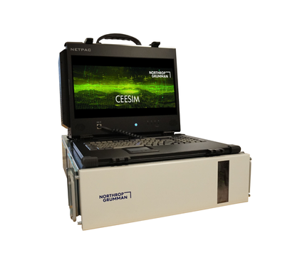
CEESIM provides the radio frequency (RF) simulation of multiple, simultaneous emitters linked to static/dynamic platforms required to faithfully simulate true combat conditions. Robust simulations offer the most affordable means of testing and validating the effectiveness of sophisticated electronic warfare equipment.
| Key Features |
| CCVPX provides cost-effective EW threat stimulus with quick delivery |
| High fidelity RF stimulus based on digital technology |
| Full scenario/emitter compatibility with trusted and market tested CEESIM product line |
| Provides compatibility with full-size CEESIM systems |
| CEESIM and mini-RFGEN (mRFGEN) configurations available |
| 20 MHz to 40 GHz frequency coverage |
| Transport case or rack packaging available |
| Benefits | |
| Low Cost/Quick Delivery | Cost is comparable to other commercial small simulators, but with all the power and capabilities of our full-sized CEESIM. Quick turn delivery is available. |
| Small Footprint | CCVPX provides the greatest flexibility and expandability of any small EW simulator available. What takes racks full of other suppliers’ hardware can be done with a few desktop CCVPX chassis. |
| High Fidelity Performance | CCVPX is a DDS source capable of generating complex intrapulse modulations that can vary on a pulse-to-pulse basis, with proven accuracy to validate the parameter extremes in threat intelligence databases. CCVPX can also generate high emitter density (up to one MPPS/channel). |
| Compatibility | CCVPX maintains full scenario/emitter compatibility with all CEESIM systems and uses the same user interface, hardware modules and tools employed in full-sized CEESIMs. |
| Confidence | CEESIM is the established threat source used to validate all state-of-the-art EW platforms. CEESIM emitter modes have gone through multiple TRVALs on U.S. programs to validate they are true representations of the threat radar waveform. CCVPX has demonstrated support of all test environments, including: Sub-assembly Test Stations, SILs, Anechoic Chambers, and Open-Air Test Ranges. |
| Core Building Blocks | The Local Oscillator (LO) and Up-converter Direction Finding (UCDF) RF slice pair provides 0.5 to 18 GHz signal generation, and the core building blocks of the Compact CEESIM-VPX. Frequency extension RF slices are available to expand this base frequency coverage. The Ultra-Low Band (ULB) RF slice extends frequency range down to include 20 to 500 MHz and the Millimeter Wave (MMW) slice extends frequency range to include 18 to 40 GHz. |
| Benchtop Solutions | Benchtop solutions consisting of a single 3U VPX chassis are ideal for lower level test stations, anechoic chambers, and open air test ranges. |
| Emitter Modeling & Visualization | The CCVPX comes with software that allows the user to define even the most complex threat radar waveforms by specifying a sequence of segments that describe the radar’s behavior in frequency, PRI, pulse, and scan. Segments of each type can trigger the other segment types to advance in their sequences to produce an accurate progression of the waveform over time. The software includes the ability to graph twelve critical parameters of the simulated radar’s waveform to allow the operator to verify correct programming. The CCVPX software can define platforms for the simulated threat radars and the SUT. The motion of all platforms is modeled with full six degrees of freedom to allow dynamic modeling of terrain following and terrain blockage, as well as the calculation of angle of arrival effects for all signals at the SUT.
|
| 3D Scenario Visualization and Editing | CEESIM offers 3D scenario visualization and editing capability, which displays the extent of threat domes and emitter activation state. The GUI display includes range and bearing from emitter to SUT. |
| Specifications | |
| Compact CEESIM-VPX | |
| Feature | Parameter |
| Frequency Control | Direct Digital Synthesis |
| Tuning Time | 0.5 usec |
Frequency Resolution (20 MHz to 40 GHz) | 1 Hz |
| Frequency Accuracy | ±2 Hz |
| Phase Noise @ SUT Ports for 20 MHz - 18 GHz | 1 kHz offset: -95 dBc/Hz 10 kHz offset: -110 dBc/Hz 100 kHz offset: -120 dBc/Hz 1 MHz offset: -130 dBc/Hz 10 MHz Offset: -137 dBc/Hz |
| Phase Noise @ SUT Ports for 18 - 40 GHz | 1 kHz offset: ≤-92 dBc/Hz 10 kHz offset: ≤-107 dBc/Hz 100 kHz offset: ≤-117 dBc/Hz 1 MHz offset: ≤-125 dBc/Hz 10 MHz Offset: ≤-135 dBc/Hz |
Broadband Noise @ CEESIM Output Ports (20 MHz - 40 GHz) | -85 dBc/MHz (typ) |
Spurious @ CEESIM Output Ports (20 MHz - 40 GHz) | -70 dBc (typ) |
| FMOP Deviation | ±500 MHz |
| FMOP Accuracy | ±1% |
| FMOP Unlock Offset | 0 Hz |
| PMOP Resolution | 1 degree |
| PMOP Accuracy | ±2 degrees |
| Maximum MOP Sample Rate | 1280 MSPS |
| MOP Pattern Playback Capacity | Capacity Memory: 2 GB Stream I/Q from External Data Source: Yes |
| Preserve MOP pattern with TDOA | Yes |
| Phase Coherency | All emitters |
| Required Emitter Calibrations | None |
| Specifications | |
| Compact CEESIM-VPX | |
| Configuration Overview | |
| Model | Description |
| Single Channel | 0.5 GHz - 18 GHz Single Omni Output Port |
| Dual Channel | 0.5 GHz - 18 GHz Single Omni Output Port |
| Single Channel | 20 MHz - 40 GHz Single Omni Output Port |
| Single Channel | 0.5 GHz - 18 GHz with 4 Ports of Phase, Amplitude & TDOA Outputs |
Can't find what you are looking for?
Get in touch


